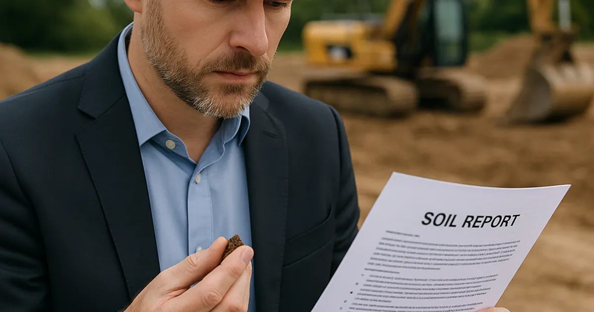
A soil report lands on your desk weeks before the first excavator rolls onto the site. It is dense, technical, and filled with classification codes, groundwater depths, and load-bearing numbers that can feel intimidating if you have never been formally trained in geotechnical engineering. Yet that document holds answers to some of the most expensive questions in earthwork planning: Can this soil support the structure? Will the ground swell or settle? How deep is bedrock? What will compaction actually cost?
Misreading or ignoring a soil report is one of the leading causes of budget overruns on earthwork projects. According to industry data compiled by the Associated General Contractors of America, subsurface surprises account for a significant share of change orders and schedule delays on civil construction projects every year. Understanding how to read a geotechnical report is not just an academic exercise. It is a direct path to protecting your margins, your schedule, and your reputation.
This guide is written for earthwork contractors, general contractors, project managers, and savvy owners who want to move from confusion to competence when a soil report hits their inbox.
What Is a Soil Report and Who Produces It
A soil report, formally called a geotechnical investigation report or geotechnical engineering report, is a document prepared by a licensed geotechnical engineer following a systematic investigation of subsurface conditions at a specific site. The investigation typically involves drilling boreholes, collecting soil samples at regular depth intervals, performing in-situ field tests, running laboratory analyses on those samples, and then interpreting all of that data to provide engineering recommendations.
Geotechnical firms are hired by property owners, developers, or sometimes municipalities before design begins. The cost of a standard geotechnical investigation for a commercial site typically ranges from $3,000 to $20,000 depending on site size, number of borings, depth of investigation, and required laboratory testing. For large infrastructure projects, geotechnical budgets can reach six figures.
The report is produced by a Professional Engineer (PE) licensed in geotechnical or civil engineering. In most U.S. states, the geotechnical report must be stamped and signed by that licensed PE before it can be used for design or permitting purposes. The report is a legal document, and its recommendations carry professional liability.
From a contractor's perspective, the geotechnical report is also a contractual document. Most public project specifications and many private contracts make the geotechnical report part of the bid documents. Understanding what it says, and what it does not say, can be the difference between a profitable bid and a financial disaster.
The Anatomy of a Geotechnical Report
Every geotechnical report has a standard structure, though format and organization vary by firm and project complexity. Here is what you will typically find:
- Executive Summary or Introduction: Project description, scope of work, and a high-level summary of findings and recommendations
- Site Description: Location, topography, existing structures, site history, and any known environmental concerns
- Field Investigation Procedures: Methods used for drilling, sampling, and in-situ testing
- Laboratory Testing Program: Types of tests performed and applicable standards (usually ASTM International standards)
- Subsurface Conditions: Detailed description of soil and rock layers encountered at each boring location
- Groundwater Information: Observed groundwater depths and seasonal variation estimates
- Engineering Analysis and Recommendations: Foundation recommendations, bearing capacity values, earthwork specifications, and other design guidance
- Boring Logs and Laboratory Data: Appendices containing the raw data
- Site Plan: Map showing boring locations relative to proposed structures
For earthwork contractors, the most actionable sections are the subsurface conditions narrative, the boring logs, the groundwater information, the earthwork recommendations, and the laboratory data. Many contractors make the mistake of skipping straight to the recommendations without understanding the underlying data. That shortcut can lead to misapplication of the engineer's guidance.
Decoding the Boring Log
The boring log is the foundational data document in any geotechnical report. It is a graphical and tabular record of everything encountered as the drill rig advanced from the surface downward. Learning to read a boring log efficiently is the single most important skill for understanding subsurface conditions.
Boring Log Structure
A standard boring log contains several columns:
Sample Depth Column: Shows the depth interval for each sample, typically in feet or meters from the ground surface.
Graphic Log Column: Uses standardized symbols to represent soil and rock types visually. Dots represent sand, horizontal lines represent clay, triangles or crosses represent gravel, and diagonal hatching typically represents rock. These symbols follow conventions established by ASTM International standards, particularly ASTM D2487 for the Unified Soil Classification System.
Sample Type and Number Column: Indicates whether the sample was collected using a split-spoon sampler (SS), a Shelby tube (ST) for undisturbed clay samples, a rock core (RC), or another method.
Blow Count or N-Value Column: This is the Standard Penetration Test (SPT) result, often written as a fraction like 8/12 or as a single number like 12. The N-value is the number of blows required to drive a standard split-spoon sampler 12 inches into the ground using a 140-pound hammer dropped 30 inches. A higher N-value means denser, stiffer, or harder material. N-values below 4 indicate very soft or loose conditions. N-values above 50 (sometimes written as 50/3, meaning 50 blows for only 3 inches of penetration) indicate very dense soil or rock.
Soil Description Column: Written descriptions of the soil including color, texture, moisture content, consistency, and classification. A typical entry might read: "Medium dense, moist, brown, fine to medium SAND with trace gravel (SP)."
Classification Code: The Unified Soil Classification System (USCS) code, such as SP (poorly graded sand), CL (lean clay), CH (fat clay), GW (well-graded gravel), or ML (silt of low plasticity).
Groundwater Notations: Symbols indicating where groundwater was encountered during drilling and where it stabilized after drilling was complete.
Reading Blow Counts for Earthwork Planning
For excavation planning, blow counts tell you what kind of equipment effort and time you will need. Use this general reference table:
| SPT N-Value | Soil Consistency (Cohesive) | Relative Density (Granular) | Excavation Difficulty |
|---|---|---|---|
| 0 to 2 | Very Soft | Very Loose | Easy, may require dewatering |
| 2 to 4 | Soft | Loose | Easy |
| 4 to 8 | Medium Stiff | Medium Dense | Moderate |
| 8 to 15 | Stiff | Medium Dense | Moderate |
| 15 to 30 | Very Stiff | Dense | Challenging |
| 30 to 50 | Hard | Very Dense | Difficult, may require ripping |
| 50+ | Rock or Very Hard | Very Dense / Rock | Likely requires blasting or rock cutting |
When you see a boring log transitioning from N-values of 10 to 15 in the upper layers to N-values of 40 to 50 at depth, that is a clear signal that your excavation will become significantly harder as you go deeper. Factor that into your equipment selection and time estimates.
Understanding Soil Classification Systems
Two primary soil classification systems appear in geotechnical reports used in the United States: the Unified Soil Classification System (USCS) and the AASHTO classification system. Both appear in different contexts, and contractors working on highway or DOT projects will encounter both.
Unified Soil Classification System (USCS)
The USCS, standardized under ASTM D2487, classifies soils based on grain size distribution and plasticity characteristics. All soils get a two-letter code:
- G = Gravel, S = Sand, M = Silt, C = Clay, O = Organic, Pt = Peat
- Secondary descriptors: W = Well-graded, P = Poorly graded, L = Low plasticity, H = High plasticity
For earthwork contractors, the most important USCS distinctions are:
GW and SW (Well-graded Gravel and Sand): Excellent fill materials, compact well, stable under load. These are often the most valuable materials on a site.
GP and SP (Poorly graded): Still usable as fill in many applications but do not compact as efficiently and may have drainage implications.
SM and SC (Silty and Clayey Sands): Workable fill with moisture management. Sensitive to construction traffic when wet.
ML and CL (Low-plasticity Silt and Clay): Moderate fill material. Highly sensitive to moisture. Difficult to work during wet weather. Common in regions like the Pacific Northwest, including around the dirt exchange in Seattle market.
CH and MH (High-plasticity Clay and Silt): Problematic fill materials. Prone to significant volume change with moisture variation. Often require amendment with lime or cement for use as structural fill, or must be wasted and replaced with import material.
Pt (Peat) and Organic Soils: Unsuitable for structural fill under almost all circumstances. Must be removed and replaced.
AASHTO Classification
The AASHTO system, maintained by the American Association of State Highway and Transportation Officials, classifies soils from A-1 (excellent subgrade) through A-7 (poor subgrade), with A-1 and A-2 being granular materials and A-4 through A-7 being fine-grained materials. A-6 and A-7 soils are typically problematic for subgrade applications. Highway and DOT project specs will often reference AASHTO classifications when specifying acceptable fill or subgrade materials.
Soil Bearing Capacity: What It Means for Your Project
Soil bearing capacity is the maximum load per unit area that the soil can support without experiencing shear failure or excessive settlement. It is expressed in pounds per square foot (psf) or kips per square foot (ksf), and it is one of the most important numbers in the entire geotechnical report.
Types of Bearing Capacity
Geotechnical reports typically report two values:
Ultimate Bearing Capacity: The theoretical maximum load before soil failure. This is a calculated value and is not used directly for design.
Allowable Bearing Capacity (or Net Allowable Bearing Pressure): The ultimate bearing capacity divided by a factor of safety (typically 2.5 to 3.0) plus any settlement considerations. This is the value used by structural engineers for foundation design.
Typical allowable bearing capacity ranges by soil type:
| Soil Type | Typical Allowable Bearing Capacity |
|---|---|
| Soft Clay | 500 to 1,000 psf |
| Stiff Clay | 1,000 to 2,000 psf |
| Loose Sand | 1,000 to 2,000 psf |
| Dense Sand | 2,000 to 4,000 psf |
| Dense Gravel | 4,000 to 6,000 psf |
| Weathered Rock | 8,000 to 20,000 psf |
| Sound Rock | 20,000 to 100,000+ psf |
As an earthwork contractor, bearing capacity values directly affect your scope of work. Low bearing capacity soils at foundation depth mean the structural engineer may specify over-excavation and replacement with engineered fill, deep foundation systems (piles or piers), or soil improvement techniques like dynamic compaction or stone columns. Each of those solutions changes your earthwork scope, your material volumes, and your subcontractor relationships.
If the report shows allowable bearing capacity of 1,000 psf or less at the planned foundation elevation, expect the design team to require significant subsurface intervention. Budget for over-excavation, import fill, and additional compaction testing.
Groundwater Information and What It Means for Excavation
Groundwater data in a geotechnical report comes from two primary sources: water levels observed during drilling (called "water seepage" or "water encountered at depth") and stabilized water levels measured after the boring has been open for a period of time. The report will typically show both, because water levels during active drilling can be influenced by drilling fluids and the mechanical disturbance of drilling.
For excavation planning, the stabilized groundwater level is the more relevant number. It tells you how deep you can excavate before you will encounter groundwater in the open excavation.
Groundwater depths also vary seasonally. A geotechnical investigation performed in late summer in an arid region may show groundwater at 15 feet. The same site investigated in March after snowmelt could show groundwater at 8 feet. Good geotechnical reports will note the seasonal variation potential and provide both high and low groundwater estimates.
When your excavation depth approaches or exceeds the groundwater level, you will need a dewatering plan. Dewatering methods range from simple sump pumping in small excavations to wellpoint systems or deep wells for large, deep cuts. Dewatering costs can add $5,000 to $500,000 or more to a project depending on scale and soil permeability.
The geotechnical report's description of soil gradation also gives clues about dewatering difficulty. Clean sands and gravels are highly permeable and will yield large volumes of water quickly, requiring aggressive dewatering. Silts and clays have low permeability but can become unstable when disturbed in a wet condition.
For projects in coastal areas or regions with high water tables, like the dirt exchange in San Francisco market and the greater Bay Area, groundwater management is often the dominant cost driver in earthwork scopes.
Find or Post Dirt, Rock & Aggregate
Join thousands of contractors using DirtMatch to buy, sell, and exchange earthwork materials.
Try DirtMatch FreeLaboratory Test Data in Appendices
The laboratory testing appendix is the backbone of the engineering analysis. Each test referenced in the report corresponds to a standardized procedure, and understanding what each test measures helps you interpret the engineering conclusions.
Common Laboratory Tests and What They Tell You
Moisture Content (ASTM D2216): The ratio of water weight to dry soil weight expressed as a percentage. High moisture content in fine-grained soils signals difficult working conditions, potential stability problems, and possible need for drying before compaction.
Atterberg Limits (ASTM D4318): Determines the Liquid Limit (LL), Plastic Limit (PL), and Plasticity Index (PI = LL minus PL) of fine-grained soils. High PI values (above 20 or 30) indicate fat clays that are problematic for structural fill. PI values above 50 almost always require soil treatment or waste and replace.
Grain Size Analysis (ASTM D6913 for sieve analysis, ASTM D7928 for hydrometer): Shows the distribution of particle sizes from gravel through clay. This data determines the USCS classification and helps predict drainage behavior, compactibility, and suitability as fill.
Standard Proctor Compaction Test (ASTM D698) and Modified Proctor (ASTM D1557): Determines the optimum moisture content and maximum dry unit weight (maximum density) for a specific soil. The Modified Proctor uses higher compaction energy and is the standard for most structural fill specifications. These two numbers (optimum moisture and maximum density) are what compaction specifications reference when they require "95% of Modified Proctor."
Consolidation Test (ASTM D2435): Performed on undisturbed clay samples to predict the amount and rate of settlement under load. If the report shows high compression indices or significant consolidation potential under the proposed loads, expect the design to address long-term settlement, which may affect your fill placement sequencing.
Unconfined Compressive Strength (ASTM D2166): Measures the compressive strength of undisturbed clay or soft rock cores. Directly related to bearing capacity and slope stability calculations.
California Bearing Ratio (CBR, ASTM D1883): Measures the load-bearing capacity of subgrade soils relative to crushed limestone. Used by pavement designers to determine pavement thickness. Low CBR values (below 3) indicate poor subgrade conditions requiring special treatment or subbase improvements.
For earthwork contractors preparing bids, the compaction test data is especially critical. If the maximum dry density for the on-site clay is 110 pcf at 18% optimum moisture, and the current natural moisture is 25%, you know that material will need to be dried down by 7 percentage points before it can be compacted to specification. In humid climates, that drying may require scarifying and aerating for days, significantly increasing your cycle time and cost per compacted cubic yard.
Earthwork Recommendations Section: Reading Between the Lines
The earthwork recommendations section is where the geotechnical engineer translates all the field and laboratory data into guidance for construction. This is the section most contractors focus on, but it must be read in context with the supporting data.
Common Earthwork Recommendations to Understand
Stripping Depth: The report will typically specify how much topsoil and organics must be removed before any structural fill is placed. Stripping depths commonly range from 6 inches to 24 inches or more, depending on site conditions. Every foot of additional stripping across a large site adds significant cut volume and disposal or reuse considerations.
Subgrade Preparation: Recommendations for proofrolling, scarifying, moisture conditioning, or over-excavation at subgrade. A recommendation to proofroll with a fully loaded dump truck and repair any areas that deflect more than an inch is a standard quality control measure, but it implies that some areas may require over-excavation and replacement.
Compaction Specifications: Usually expressed as a percentage of maximum dry density from the Modified Proctor test (ASTM D1557). Typical specifications call for 90% to 95% of Modified Proctor for structural fill under buildings, and sometimes 98% for the top 12 inches of pavement subgrade. Higher compaction requirements mean more passes with heavier equipment.
Structural Fill Materials: The report will define what materials are acceptable as structural fill. This may include native soils meeting certain criteria, or it may require imported granular material. When native soils are rejected as structural fill, someone needs to source import material. That is where having efficient connections to nearby material sources becomes critical to project economics. Contractors using DirtMatch can quickly identify verified sources of import fill material close to their project sites, reducing haul distances and import costs substantially.
Unsuitable Material: Quantities and locations of material that must be removed from the site. This drives your export hauling scope and creates opportunities for material exchange if the material is clean and suitable for use elsewhere.
Temporary Slope Stability: Maximum safe cut slopes for temporary excavations, which directly affects your OSHA compliance planning for excavation safety under 29 CFR 1926 Subpart P.
Special Conditions: Watch for recommendations addressing expansive soils, collapsible soils, liquefiable sands (in seismic zones), corrosive soils (affecting buried metals and concrete), and karst conditions (in limestone regions). Each of these special conditions requires specific construction practices.
Swell and Shrink Factors: Calculating Your Real Material Volumes
One of the most practical applications of soil report data for earthwork contractors is calculating accurate swell and shrink factors for material volume estimates. These factors are the difference between your bid volume and your actual haul and compaction scope.
Swell occurs when soil is excavated and loaded into a truck. The disturbed soil takes up more volume than it did in the ground because of air voids introduced during excavation. A cubic yard of bank (in-situ) material becomes approximately 1.1 to 1.4 cubic yards of loose material in a truck, depending on soil type.
Shrinkage occurs when loose fill material is compacted. A cubic yard of loose fill compacts to less than a cubic yard of finished compacted fill. When you bring in import material and compact it to 95% Modified Proctor, the finished volume will be less than the truck-delivered volume.
Use the soil classification and density data from the geotechnical report to estimate these factors accurately:
| Material Type | Bank to Loose Swell Factor | Compaction Shrinkage Factor |
|---|---|---|
| Sandy Gravel (GW) | 1.10 to 1.15 | 0.92 to 0.95 |
| Clean Sand (SW, SP) | 1.10 to 1.20 | 0.90 to 0.95 |
| Silty Sand (SM) | 1.15 to 1.25 | 0.88 to 0.93 |
| Lean Clay (CL) | 1.25 to 1.35 | 0.85 to 0.90 |
| Fat Clay (CH) | 1.30 to 1.40 | 0.80 to 0.88 |
| Weathered Rock | 1.40 to 1.50 | 0.95 to 1.00 |
| Solid Rock | 1.50 to 1.70 | 0.95 to 1.00 |
Understanding these factors from the geotechnical data allows you to convert plan quantities (in bank cubic yards) to truck quantities and compacted fill quantities accurately. Contractors who ignore swell and shrink calculations routinely under-bid import or export hauling by 15% to 30%.
When you have cut material that is suitable for reuse but is not needed on your current project, connecting with nearby projects that need fill can eliminate disposal costs entirely. The DirtMatch platform was built specifically to facilitate these material exchanges between contractors, making it straightforward to find a home for excess cut or to source quality import material without the traditional broker markup.
Red Flags to Watch for in Any Soil Report
Not all geotechnical reports deliver good news. Here are the conditions that should immediately trigger further investigation, budget review, or risk discussions with the project team:
Organic Content Above 3%: Organic material in structural fill zones will decompose over time, causing long-term settlement. Any soil with significant organic content must be removed from beneath structural areas.
Plasticity Index Above 30: High PI clays are expansive. In Texas, Colorado, and many western states, expansive clay (sometimes called adobe or black cotton soil) can exert tremendous uplift pressure on foundations and pavements. The dirt exchange in Denver region, for example, frequently encounters highly plastic Bentonite-rich clays that require careful earthwork handling.
Liquefaction Potential Noted: In seismic zones, loose saturated sands can liquefy during earthquakes. If the report flags liquefaction potential, the structural engineer may require ground improvement such as vibro-compaction or stone columns.
Perched Groundwater: Water sitting on top of a less permeable layer at a depth above the main water table. Perched water conditions can surprise excavation crews even when the reported main groundwater depth seemed acceptable.
Refusal at Shallow Depths: When boring logs show refusal (50 blows for less than 6 inches of penetration) at shallow depths, you may have boulders, cobbles, or shallow bedrock that will require rock-breaking equipment or blasting. This is a critical cost driver that must be priced carefully.
Limited Number of Borings: A site with only one or two borings has high subsurface uncertainty. The fewer the borings, the greater your risk of encountering conditions that differ from what the report describes. Some contractors include a differing site conditions clause in their contracts for exactly this reason.
Contamination Flags: References to discolored soil, petroleum odors, debris, or elevated readings on organic vapor meters during drilling are serious red flags. Contaminated soil requires special handling, testing, and permitted disposal that can add tens of thousands of dollars to earthwork costs. The EPA Brownfields Program provides guidance on contaminated property assessment and remediation that is worth reviewing if your project site has any history of industrial use.
Using the Soil Report to Build a Better Bid
Once you understand the contents of the geotechnical report, the next step is translating that understanding into a more accurate and competitive bid. Here is a systematic approach:
Step 1: Quantify the unsuitable material volumes. Cross-reference the boring logs and the site plan to estimate the volume of peat, organic soil, soft clay, or other unsuitable material that must be removed. Map this by area and depth.
Step 2: Determine native material reuse percentage. Based on the lab data and earthwork recommendations, estimate what percentage of cut material can be reused as structural fill on-site versus what must be exported as waste.
Step 3: Calculate import fill requirements. If native material is insufficient in quantity or quality, determine the volume of import material needed. Identify potential sources, haul distances, and material costs.
Step 4: Price the moisture conditioning work. If native soils are above optimum moisture content for compaction, estimate the time and cost for drying. If they are below optimum, estimate water addition costs.
Step 5: Price dewatering if needed. If excavation depth exceeds the reported groundwater level, get a dewatering subcontractor involved in the bid process early.
Step 6: Apply appropriate swell and shrink factors. Convert all plan quantities to truck and compacted quantities using factors consistent with the soil types identified in the report.
Step 7: Identify rock or hard material contingency. If boring logs show high blow counts or refusal at depths within your excavation zone, include a unit price or allowance for rock excavation.
Step 8: Review slope stability recommendations. Confirm that your temporary excavation slopes comply with OSHA requirements and the geotechnical engineer's recommendations. For detailed federal requirements on excavation safety, the OSHA Trenching and Excavation guidance is the authoritative reference for soil classification and protective systems.
For contractors who regularly need to source import fill or move excess cut material, integrating a material exchange platform into this bidding workflow can meaningfully change project economics. DirtMatch Pro gives contractors priority access to verified fill sources and receiving sites across their region, helping you lock in material costs at bid time rather than scrambling after award.
Comparing the Soil Report to Field Conditions During Construction
Even the best geotechnical report is an interpretation of limited point data extrapolated across a larger area. Boring logs represent conditions at specific locations on specific dates. Actual subsurface conditions between boring locations are estimated, not measured. This is the fundamental limitation of geotechnical investigation, and it is why experienced earthwork contractors track field conditions carefully during construction.
Maintain a simple daily log of:
- Actual excavation conditions versus reported conditions
- Groundwater depth compared to reported groundwater level
- Any unexpected materials encountered (boulders, debris, soft zones, discolored or odorous soil)
- Compaction test results versus specification requirements
- Equipment production rates versus planned rates
When field conditions differ materially from the geotechnical report, you have the basis for a differing site conditions claim under most public contracts, or a change order discussion on private work. Documentation is everything. A daily log with photos is your best evidence.
Communicate promptly with the project engineer when unexpected conditions are encountered. Do not continue excavating through contaminated soil, unexplained voids, or extremely soft zones without notifying the design team. Proceeding without notification can jeopardize your change order claim and potentially your liability exposure.
Summary: Building a Pre-Construction Soil Report Checklist
Before you mobilize on any earthwork project, work through this checklist using the geotechnical report:
- Confirm the number, location, and depth of borings relative to your work area
- Identify all soil types using USCS codes and note their location and depth ranges
- Record groundwater depths and seasonal variation estimates
- Note all blow counts greater than 30 or showing refusal within your excavation zone
- Review compaction specifications and compare optimum moisture to reported natural moisture
- Identify all unsuitable material by type, location, and estimated volume
- Check for any special conditions: expansive clays, organics, contamination flags, liquefiable soils
- Confirm allowable bearing capacity at foundation elevation and compare to structural design loads
- Document any areas with limited boring coverage (high uncertainty zones)
- Note all recommended subgrade treatments and factor them into your production schedule
The time you invest in thoroughly understanding the geotechnical report before mobilization pays dividends throughout the project. Contractors who read the soil report carefully bid more accurately, manage risk more effectively, and avoid the painful surprises that destroy project profitability.
Whether you are working a small residential cut-and-fill in suburban Denver or a large grading contract for a commercial development in the Los Angeles basin, the soil report is your roadmap to the world beneath the surface. Read it carefully, ask questions when something is unclear, and use the data to make smarter decisions at every stage of your earthwork project.